

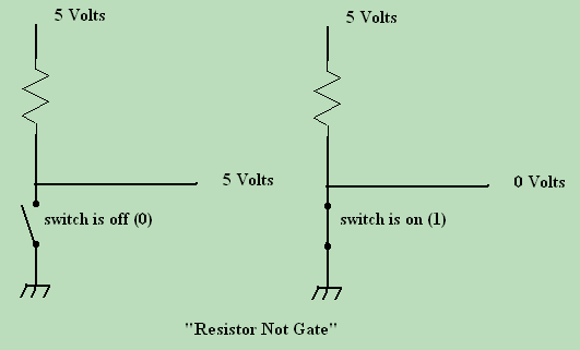
 Having studied how the relay logic circuits work, you should have a smooth transition to the solid state logic circuits. Lets begin with something that is NOT quite "solid state" first. The resistor "NOT" gate. Having studied how the relay logic circuits work, you should have a smooth transition to the solid state logic circuits. Lets begin with something that is NOT quite "solid state" first. The resistor "NOT" gate.
Note that when the switch is open (turned off - indicating a zero), you get a 1 on the output (5 volts out). If you then flip the switch to close or short it (turn the switch on - indicating a 1), the current finds its way South, and because of the voltage drop across the resistor, you now have a 0 at the output. So with the switch ON, the output of the circuit turns OFF, but with the switch OFF, the output turns ON. This is the textbook definition of a "NOT" gate. The resistor value is somewhat critical here. In order for this circuit to work, the resistor must be of a low enough value that the voltage drop allows a +5V (high state) when the switch is open. If the value is too high, the load from the following circuit will cause it not to be low all the time, or unstable. 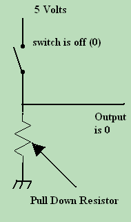 You will note that this works via a type of logic called "PULL-DOWN" logic. Pull down logic requires a special component called the "PULL-UP" resistor. If the input to the next circuit had no resistor tie to the +5 line (or if the resistor were open), it would just float around, and not be a very reliable circuit. If we tie the input directly to the +5 volt line, then it would ride high with the switch open, but the moment we closed the switch, maximum (infinite) current would flow from the power supply to the switch (because there is no resistor to slow it down) - if we were lucky it would blow a fuse. If we were unlucky, you'd be reading how to repair a burned up circuit board trace in the soldering course. You will note that this works via a type of logic called "PULL-DOWN" logic. Pull down logic requires a special component called the "PULL-UP" resistor. If the input to the next circuit had no resistor tie to the +5 line (or if the resistor were open), it would just float around, and not be a very reliable circuit. If we tie the input directly to the +5 volt line, then it would ride high with the switch open, but the moment we closed the switch, maximum (infinite) current would flow from the power supply to the switch (because there is no resistor to slow it down) - if we were lucky it would blow a fuse. If we were unlucky, you'd be reading how to repair a burned up circuit board trace in the soldering course.
In order to keep the next stage at a high input, and not blow the fuse (or worse) we need some kind of resistance between the switch and the +5V line. That resistor is called the pull-up resistor. Its job is to keep the input to the next stage high (+5V) until the switch is thrown, then it allows the input to go low (0V) without causing any damage. On the flip side (pardon the pun) if we put the switch BELOW the input line (on the ground or low side instead of the 5V or high side), then it is a "pull-down" resistor. In this case, the input to the next stage is normally a one, until the switch is closed, and the resistor pulls it down to a zero. 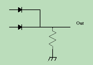 Now lets add a few semiconductor diodes to the mix. If we eliminate the 5 Volt input, and substiute it with 2 diodes to the input of our pull down resistor - what do we get? Lets build a small logic table and see how it pans out. Now lets add a few semiconductor diodes to the mix. If we eliminate the 5 Volt input, and substiute it with 2 diodes to the input of our pull down resistor - what do we get? Lets build a small logic table and see how it pans out.
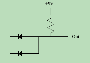 If we now take the circuit and spin it around a little, we come up with this configuration. Note that instead of a pull-down resistor, we have a pull up this time. That resistor is chosen to have a very high level of resistance this time, such that if either of the diodes has a low input, the output will not go high, but will remain low. If however, BOTH diodes have a high input, then the output of the circuit is high. Clearly this is a diode AND gate. If we now take the circuit and spin it around a little, we come up with this configuration. Note that instead of a pull-down resistor, we have a pull up this time. That resistor is chosen to have a very high level of resistance this time, such that if either of the diodes has a low input, the output will not go high, but will remain low. If however, BOTH diodes have a high input, then the output of the circuit is high. Clearly this is a diode AND gate.
Diode and resistor logic circuits are functional, and they are used extensively in discrete electronic circuitry, but they are almost never "cascaded" (put in series), and they are never implemented in integrated circuits. You might ask why? The answer lies in the fact that they are resistive. They drain energy from the circuit, and as such, if they are cascaded, the voltage level in circuits that follow them may drop so low as to be unstable. The answer for this problem is GAIN. Ok you bunch of free loaders. You telling me you haven't learned ANYTHING? Click the links below will ya? I'm starvin' here! |
| (On The Following Indicator... PURPLE will indicate your current location) | ||||||||||||||||||||||||
| 1 | 2 | 3 | 4 | 5 | 6 | 7 | 8 | 9 | 10 | 11 | 12 | 13 | 14 | 15 | 16 | 17 | 18 | 19 | 20 | 21 | 22 | 23 | 24 | 25 |
| 26 | 27 | 28 | 29 | 30 | 31 | 32 | 33 | 34 | 35 | 36 | 37 | 38 | 39 | 40 | 41 | 42 | 43 | 44 | 45 | 46 | 47 | 48 | 49 | 50 |
| 51 | 52 | 53 | 54 | 55 | 56 | 57 | 58 | 59 | 60 | 61 | 62 | 63 | 64 | 65 | 66 | 67 | 68 | 69 | 70 | 71 | 72 | 73 | 74 | 75 |
[COURSE INDEX] [ELECTRONICS GLOSSARY] [HOME]
| Otherwise - please click to visit an advertiser so they know you saw their ad! |
