

|
So far, we've discussed the basic operation of the following Analog chips, and tried to cover some decent test equipment you can build for your home lab out of these basic chips:
While we won't be building any projects from most of these - you should be familiar with the basic operation of each of these digital devices as well, as you will see them commonly in the field.
Note that the above links point to the manufacturer's data sheets on each microchip. 7400 Series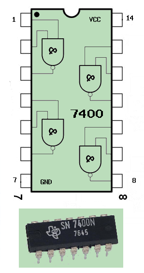 The 7400 series of chips is a family of logic chips, not unlike the logic transistor circuits we've already discussed. In particular, the 7400 contains 4 seperate NAND gates in one small package. This is commonly known as a Quad 2 Input NAND gate. Other common packages are:
555/556 TimersOne of my all time chips - this is a utility tool for every electronics engineer's toolkit. This chip is useful as a clock or an oscillator, as well as a trigger, and many other possibilities. In essence, it is a modified flip/flop - specifically designed for precision timing. Timing being considered the RC time constant between pins 3 and 2. 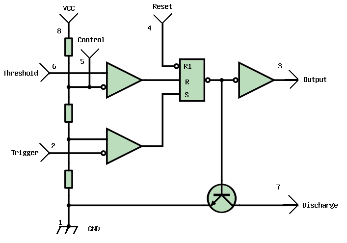 Bias is applied across pin 8 with ground on 1. This chip is able to handle a WIDE variety of bias voltages, from 3 to 13 Volts! Like a standard Flip Flop, there is both a Set and Reset, albeit they are internal. The Trigger on pin 2 acts as the Set. When voltage on pin 2 goes low, it causes pin 3 (OUT) to go high. Pins 5 and 6 work together. Pin 5 sets a "control voltage (typically .6 to .7 volts - typical e-b junction biasing for a silicon transistor). When pin 6 rises ABOVE the voltage at pin 5, the timing interval ends. Pin 7 is usually used to discharge a capacitor between timing intervals, although pin 4 can interrupt a timing interval at any time by shorting it to ground. Bias is applied across pin 8 with ground on 1. This chip is able to handle a WIDE variety of bias voltages, from 3 to 13 Volts! Like a standard Flip Flop, there is both a Set and Reset, albeit they are internal. The Trigger on pin 2 acts as the Set. When voltage on pin 2 goes low, it causes pin 3 (OUT) to go high. Pins 5 and 6 work together. Pin 5 sets a "control voltage (typically .6 to .7 volts - typical e-b junction biasing for a silicon transistor). When pin 6 rises ABOVE the voltage at pin 5, the timing interval ends. Pin 7 is usually used to discharge a capacitor between timing intervals, although pin 4 can interrupt a timing interval at any time by shorting it to ground.
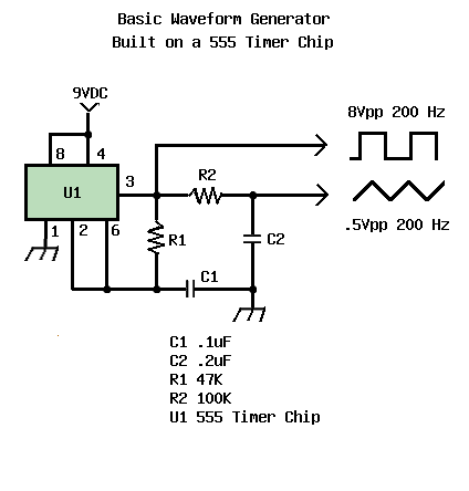 Included is a handy circuit you can modify to fit your own needs. It is a simple waveform generator, capable of making both square and triangle (sawtooth) waves. Of course, the wave forms could be shaped to be sine waves, etc - with the right RC filtering following it. You can also vary the frequency and pulse width by changing the values of R1/C1 respectively. As is it generates a signal at roughly 200 hz - a nice genle low tone if you play it into a speaker. Add switches, variable resistors, etc and play with it. HAVE FUN! Included is a handy circuit you can modify to fit your own needs. It is a simple waveform generator, capable of making both square and triangle (sawtooth) waves. Of course, the wave forms could be shaped to be sine waves, etc - with the right RC filtering following it. You can also vary the frequency and pulse width by changing the values of R1/C1 respectively. As is it generates a signal at roughly 200 hz - a nice genle low tone if you play it into a speaker. Add switches, variable resistors, etc and play with it. HAVE FUN!
|
| (On The Following Indicator... PURPLE will indicate your current location) | ||||||||||||||||||||||||
| 1 | 2 | 3 | 4 | 5 | 6 | 7 | 8 | 9 | 10 | 11 | 12 | 13 | 14 | 15 | 16 | 17 | 18 | 19 | 20 | 21 | 22 | 23 | 24 | 25 |
| 26 | 27 | 28 | 29 | 30 | 31 | 32 | 33 | 34 | 35 | 36 | 37 | 38 | 39 | 40 | 41 | 42 | 43 | 44 | 45 | 46 | 47 | 48 | 49 | 50 |
| 51 | 52 | 53 | 54 | 55 | 56 | 57 | 58 | 59 | 60 | 61 | 62 | 63 | 64 | 65 | 66 | 67 | 68 | 69 | 70 | 71 | 72 | 73 | 74 | 75 |
[COURSE INDEX] [ELECTRONICS GLOSSARY] [HOME]
| Otherwise - please click to visit an advertiser so they know you saw their ad! |
