

Lesson 55 - Biasing & Configuration of AmplifiersBut there are many types of amplification. The basic definition is to raise a level, or to increase gain. We can have a circuit raise the Current level, and it becomes a Current amplifier. We can have it raise a Voltage level, and it becomes a Voltage Amplifier. Or we can make it raise the level of Watts, and it is a Power Amplifier. Both the transistor and tube are capable of performing all three tasks, and in this lesson and the next, you will see that they both do it in a similar manner. Let's begin with tubes, shall we? Biasing, of course, simply deals with setting voltages to control the operating point - or quiescent state - of the amplifier. Configuration deals with how the amplifier is laid out in the circuit. Both combined can contribute to how the amplifier operates, as well as what the class of the amplifier will be. In most schematics, signal passes from the left side of the page (input) to the right side of the page (output). With a 2 terminal component, like a diode or a resistor, each side of the component is typically connected to either the input or the output. Active components such as transistors and tubes, have a minimum of 3 terminals. Three terminal components will have one terminal connected to the input, one to the output.... but what happens to the third? We say that it is common to both the input and the output. If, lets say, it is a tube... the grid can be in the input, and the plate/anode in the output. What part of the circuit would the cathode be in then? Well, typically, it is "grounded", and as such, is common to both the input and output. This configuration would be called a grounded cathode, or common cathode. The equivalent to this would be a common emitter configuration in a transistor. I common emitter configuration, the base is on the input, and the collector the output. By far, this is the most common configuration you will see transistors in. 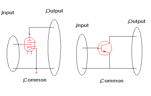
While it features relatively high gain, good frequency response, high input impedance, medium-to-low output impedance, this configuration is probably used the most because it is the easiest to understand, and it is the one that is used the most. This may sound like a circular argument - but if you were to "copy" (reverse-engineer) a working circuit to make your own, wouldn't you use the one that is most common - provided it would fit the bill? On the other hand, what if the emitter is used as the input, and the collector as the output. This would be common grid, or grounded grid configuration. The equiv in tubes would be a common base, or grounded base. Common grid doesn't have as high gain as common cathode, but it has better linearity. This is because the grid is neutral with respect to the input and output. In theory - very little or no current flows through the grid circuit, so there is little chance of distortion between the input and output circuits, unless of course it is caused by other components in the circuit. 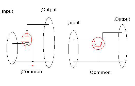
Finally, we have a common plate/cathode or common collector circuit. Common plate is an interesting circuit, in that tubes only operate from negative to positive with respect of anode to cathode. 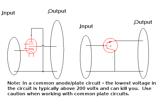 In otherwords - In order for the plate to be common, and the plate has to ride at 250V+/-... the input to the plate has to ride on a very high voltage, and typically the output must also ride on a high voltage. Because of this - common plate often can have a good current gain, but typically NO voltage gain whatsoever. In a transistor circuit, the common collector is often referred to as an emitter follower. Emitter follower circuit are often used as operational amplifiers (op amps) or feedback amplifiers. This is because they have high input impedance and low output impedance, which makes them ideal for impedance matching. Like their tube counterparts, they have good current gain, with no voltage gain. 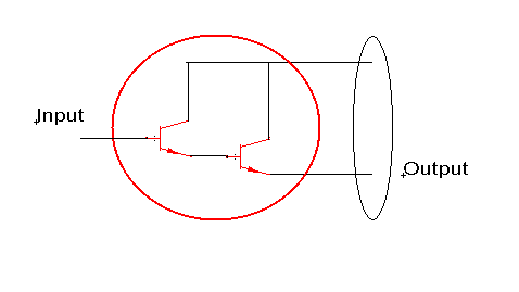 Emitter Follower configuration is used in "Darlington" amplifiers, which have 2 transisters connected cascading, with the emitter of one directly feeding the base of another, and both of the collectors are commonly connected. Darlingtons have extremely high current gain with a high input impedance, which reduces the possibility of impedance mismatching. In general, GAIN=Signalout / Signalin. so if we are talking about
Not a difficult formula to remember - so I won't ask you to. Your teacher at school might though. Each of these configurations have their own purpose, strengths, and weaknesses, but rest assured - if you dabble in electronics long enough - you'll run into all of them. 
|
| (On The Following Indicator... PURPLE will indicate your current location) | ||||||||||||||||||||||||
| 1 | 2 | 3 | 4 | 5 | 6 | 7 | 8 | 9 | 10 | 11 | 12 | 13 | 14 | 15 | 16 | 17 | 18 | 19 | 20 | 21 | 22 | 23 | 24 | 25 |
| 26 | 27 | 28 | 29 | 30 | 31 | 32 | 33 | 34 | 35 | 36 | 37 | 38 | 39 | 40 | 41 | 42 | 43 | 44 | 45 | 46 | 47 | 48 | 49 | 50 |
| 51 | 52 | 53 | 54 | 55 | 56 | 57 | 58 | 59 | 60 | 61 | 62 | 63 | 64 | 65 | 66 | 67 | 68 | 69 | 70 | 71 | 72 | 73 | 74 | 75 |
[COURSE INDEX] [ELECTRONICS GLOSSARY] [HOME]
| Otherwise - please click to visit an advertiser so they know you saw their ad! |
