

|
Along the way, as with tubes, the semiconductor diode has evolved. One of the first semiconductor diodes invented was the Shockley diode (Named after William Shockley of AT&T fame). Sometimes a Shockley diode is called a PNPN or 4 layer diode to differentiate it from other diodes. Not to be confused with the Schottky diode, the Shockley had 2 N regions and 2 P regions. While the Shockley diode is no longer manufactured, the Thyristor, or Silicon Controlled Rectifier, can be substituted if necessary - we'll explain later. 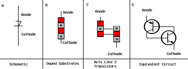
If you look at the image above (b), you get an idea of how the Shockley diode is constructed. It is actually built in alternating layers of P, then N doped semiconductor material. However, this gives you no clue as to how the device actually functions! In reality, if you mentally separate the top section, then the bottom section, you see that in reality it is (c) 2 Bipolar transistors - a PNP and an NPN, joined with direct coupling, and in fact, it acts that way (c and d in the image above). 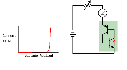
Note the circuit. We have a battery, an "infinately" variable resistor, a Shockley diode, and an Ammeter. We begin with the resistor having infinate resistance, no current is flowing whatsoever. As we slowly decrease resistance, even with no base voltage applied, we reach a "breakdown voltage" (some texts call this the breakover voltage) where the voltage is high enough to force through internal resistances, and current begins to flow through our "first transistor". Once it begins to conduct, it provides base voltage for the "second transistor", which turns on, allowing a strong current flow through the entire circuit. At this point, the diode is "on" and will stay on until nearly all voltage is removed. In this condition, it is said to be "latched" on. 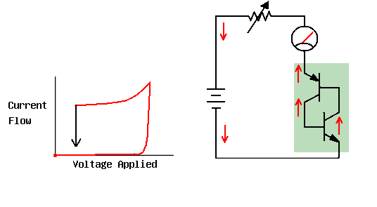
Now let us begin to increase resistance again. Since the Schockley Diode is already conducting, even if we now lower the voltage, the diode does not have to battle the "breakdown voltage" any more (as it is already broken down), and it can simply continue to conduct current at a lower level of voltage. Finally, at some voltage level, it simply refuses to conduct any further, and quite suddenly drops in current altogether. 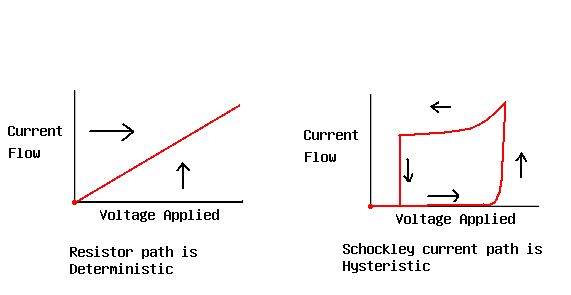
Note that here we introduce an interesting principle called "Hysteresis". If we follow the "current path" on a graph (as we have been) we notice something interesting. On a simple device like a resistor, (think Ohm's Law for a moment), as we increase the voltage, the current increases. We can predict at any given time what the current is going to be, by knowing the voltage applied, because the resistance does not change. In the SCR, we can be at the same voltage level, and have 2 different currents - depending on whether we are ramping up the voltage, or dropping the voltage after we've reached the breakdown point. In other words - we have a variable resistance device, and all variable resistance devices exhibit some form of Hysteresis. In a common transistor, we can plot a similar curve by varying the base voltage, or the same by varying the grid voltage in a tube. 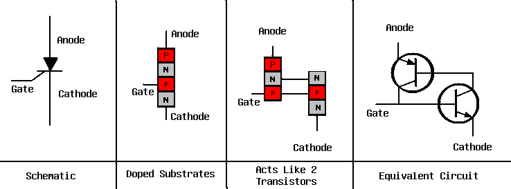
The Silicon Controlled Rectifier (or SCR), otherwise known as the "Thyristor" is simply a build up from the Schockley Diode that we've already discussed. Take a look at the image above. Like the Schockley Diode, it has 4 sections (PNPN), but it has a gate on the second P doped section. If we leave the gate floating (unconnected) the SCR behaves exactly like a Shockly diode. However, if we add a voltage to the gate, something interesting happens. 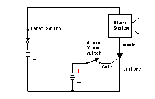 Because the gate is connected to the base of the second transistor, it can be used as an alternative means to latch the SCR. Even though there is not enough voltage drop from the Anode to the Cathode to cause a breakover to happen, once the gate voltage is applied, the SCR goes into latch mode. Then even if the gate voltage goes away, current continues to flow from Anode to Cathode, as if it had the breakdown voltage reached.
Once the SCR is triggered, it latches into a continual ON state. The only reliable way to turn it off is to remove power from the SCR altogether. I say reliable, because in some circumstances (but not all), it MAY be possible to turn it off by shorting the Gate connection to the Anode connection. This does not always work and therefore is considered unreliable. Why would someone want a circuit you can't turn off? Consider a burglar alarm. The thief opens a window, which has a magnetic switch on it. That turns on the alarm, and a siren goes off. You don't want the alarm to turn back off just because he shut the window again. This is a perfect use for an SCR. Another common use for it is in surge protection circuitry. Assume you have a voltage surge to a very high voltage circuit. Too high of a voltage could damage very expensive parts, so you have an SCR in line with it. When a spike appears on the line, it triggers the SCR. The SCR turns on and triggers a relay contactor, which shuts off the power to the device. Power remains turned off until you get to the site to insure that there is no longer a high voltage danger to your expensive equipment. When very high voltage applications exist, instead of using an SCR controlled contactor, one might choos instead to use its older cousin - the Thyratron. A thyratron is build in similar fashion to a Triode vacuum tube, however it is filled with gas such as argon or mercury vapor instead of having a vacuum. Because it is filled with the gas, it does not have the linear characteristics of a traditional vacuum tube, and can not typically be used for amplification. It is normally used as a high voltage latching circuit - much like described above - only without the need of the relay/contactor. If you run into a Thyratron in your travels, it is a safe bet that it is being used as a high voltage latch circuit. Be careful not to break these open and snort the gas, as I hear mercury vapor is NOT good to breathe. |
| (On The Following Indicator... PURPLE will indicate your current location) | ||||||||||||||||||||||||
| 1 | 2 | 3 | 4 | 5 | 6 | 7 | 8 | 9 | 10 | 11 | 12 | 13 | 14 | 15 | 16 | 17 | 18 | 19 | 20 | 21 | 22 | 23 | 24 | 25 |
| 26 | 27 | 28 | 29 | 30 | 31 | 32 | 33 | 34 | 35 | 36 | 37 | 38 | 39 | 40 | 41 | 42 | 43 | 44 | 45 | 46 | 47 | 48 | 49 | 50 |
| 51 | 52 | 53 | 54 | 55 | 56 | 57 | 58 | 59 | 60 | 61 | 62 | 63 | 64 | 65 | 66 | 67 | 68 | 69 | 70 | 71 | 72 | 73 | 74 | 75 |
[COURSE INDEX] [ELECTRONICS GLOSSARY] [HOME]
| Otherwise - please click to visit an advertiser so they know you saw their ad! |
