

The Meter Made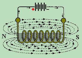 If we allow a current to flow through a coil of wire, it will generate a magnetic field. That magnetic field can be used to move nearby permanent magnets or ferrite metal components. We say that there is an induced magnetic field radiating from the coil of wire. When the induced magnetic field cuts, or passes through, the magnetic field of the permanent magnet, it has the same effect of two magnets cutting each other's fields. In other words, it attracts or repels according to polarity.
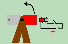
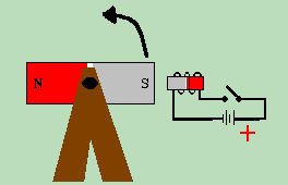
 The important point here is that we can use electromagnetic energy to make something turn, which brings us to one of the greatest leaps in electronic advancement - the D'ARSONVAL MOVEMENT. The D'Arsonval movement is the basis for all early metering devices, and is still in common use today. There are 5 basic parts to a D'Arsonval movement.
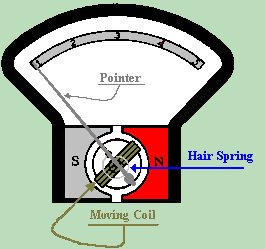
Permanent Magnet

Coil

Hair Spring

Pointer

Scale
In the D'Arsonval movement, the permanent magnet is fixed. It is the coil which does the turning. The coil is mounted on a needle fine axle, which would allow the coil to spin 360 degrees. The hair spring is used to return the needle to its original position, as well as to regulate the movement of the meter. The pointer, which is attached to the turning coil, is used for an indicator of how far the coil has turned. Finally, the scale is used as a numerical standard to compare readings. The D'Arsonval movement can be used by itself as a standalone instrument called a GALVANOMETER. The galvanometer is a device which indicates the presents of electrical current. It is not calibrated for Ohms, Volts, or Amps. By adding a high resistance in series with the D'Arsonval movement, we create a VOLTMETER. A Voltmeter is a device used to measure electrical potential in Volts. The series resistor is called a MULTIPLIER, and its purpose is to limit the flow of current through the fragile meter movement. Given a known resistance, the Voltage read at the leads of a Voltmeter can be exactly calculated to cause a certain amount of current to flow through the coil of the meter. Armed with Ohms Law, and knowing the value of the resistor we use, we can calibrate the meter's scale to measure an exact amount of Voltage. We know that: 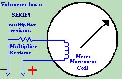
     E  Where: R = Multiplier Resistance

R = ---        E = Full Scale Voltage

     I         I = Full Scale Reading

                   of Meter
So it follows that given a meter movement that deflects full scale when 1 milliampere flows through it, We can find the value of the multiplier resistor that is necessary by using the following formula:
     1000 x E

R = ---------

         I
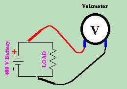
If we measure the Voltage across the circuit in the diagram above, we find that E = 400 Volts.
(NOTE THAT VOLTAGE IS ALWAYS MEASURED IN PARALLEL),
     1000 x 400     400K

R = -----------  = ---------

        I          1.0 Amps
Knowing, then, that we have a 400KW Resistor, and it requires a 400 Volt potential to cause full deflection we divide the meter resistance by the full scale voltage and come up with the sensitivity of the meter.
       meter

     resistance     400K Ohms

R = -----------  = --------- = 1000 Ohms per Volt sensitivity.

    full scale      400 Volts

      voltage
|
| (On The Following Indicator... PURPLE will indicate your current location) | ||||||||||||||||||||||||
| 1 | 2 | 3 | 4 | 5 | 6 | 7 | 8 | 9 | 10 | 11 | 12 | 13 | 14 | 15 | 16 | 17 | 18 | 19 | 20 | 21 | 22 | 23 | 24 | 25 |
| 26 | 27 | 28 | 29 | 30 | 31 | 32 | 33 | 34 | 35 | 36 | 37 | 38 | 39 | 40 | 41 | 42 | 43 | 44 | 45 | 46 | 47 | 48 | 49 | 50 |
| 51 | 52 | 53 | 54 | 55 | 56 | 57 | 58 | 59 | 60 | 61 | 62 | 63 | 64 | 65 | 66 | 67 | 68 | 69 | 70 | 71 | 72 | 73 | 74 | 75 |
| Otherwise - please click to visit an advertiser so they know you saw their ad! |
