

Dangerous Curves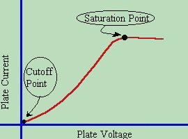 As discussed in the previous lesson, a Characteristic Curve is found by
applying several different voltage levels, and measuring plate voltages vs.
plate current. We note that in a diode, if we go below a certain plate
voltage, ( in this case 0 volts ) no plate current flows. The minimum point at
which the tube no longer operates is called the
CUTOFF POINT
. Above a certain plate voltage, additional plate voltage has very little
effect in increasing the plate current. The maximum point where raising the
plate voltage no longer increases current is called the
SATURATION POINT
.
As discussed in the previous lesson, a Characteristic Curve is found by
applying several different voltage levels, and measuring plate voltages vs.
plate current. We note that in a diode, if we go below a certain plate
voltage, ( in this case 0 volts ) no plate current flows. The minimum point at
which the tube no longer operates is called the
CUTOFF POINT
. Above a certain plate voltage, additional plate voltage has very little
effect in increasing the plate current. The maximum point where raising the
plate voltage no longer increases current is called the
SATURATION POINT
.
In reality, there are two different factors involved in the control of the amplitude ( or level ) of the plate current that flows in a diode. These are the filament voltage ( sometimes called the heater voltage ), and the plate voltage. Remember that the cathode must be HEATED into thermionic emission. The temperature of the cathode must be high enough to "boil" the electrons from its surface. It stands to reason, that the higher the temperature we heat the cathode to, the more electrons will be "boiled off". Much like raising the temperature of a pan of water causes it to boil away into steam faster. There does come a point though, where we can boil the electrons off no faster. As we raise the voltage on the heater, it will actually begin to slow down the movement of electrons toward the plate, and begin drawing them toward the heater itself. The underlying reason for this is the space charge itself. As the electrons get boiled off, it causes the overall electrical charge of the cloud of electrons to grow. At some point, the cloud of electrons reaches a high enough negative charge that it repels any new electrons being boiled off, and they return back to the filament - or have to overcome so much of an opposing force from the cloud that they simply never leave it at all. Therefore, when setting up a tube for operation, you want to make sure that you don't set the filament voltage of the tube so high that it will cause this effect, as it will reduce the efficiency, as well as the life expectancy of the tube. Most tubes are operated at standard values of 6 or 12 Volts. It is typically considered good practice to begin with a new tube somewhat under that (say 5.0 or 5.5 volts assuming a 6 volt tube) and run it that way until the tube gets older and begins to soften. Often, if a tube gets weak and doesn't output its rated power anymore, you can boost, say a 6 Volt filament to run as high as 7.5 or even 8 Volts. This may extend the life of the tube for a while, but you must watch the plate current. If plate current begins to drop off, then you have the filament voltage set too high. For longest life of a tube, the rule of thumb is to run the tube at the lowest filament voltage that will make the current necessary for proper operation of the device. This maximizes the life expectancy of the tube. Now the question might arise in one's mind, "Why on earth would someone go through all that effort to keep the $10 tube of a guitar amplifier a few more months?" The answer is that they wouldn't. However - If we are talking about a $30,000-$60,000 final output tube of a broadcast transmitter - the picture changes quite a bit. I've taken tubes that were rated to last 5-7 years, and extended their lives to 10-15 years by this method. And if you can squeeze 3 more years out of a $60,000 tube... you've saved the company thousands of dollars. Companies tend to be grateful for that and reward you with a higher paycheck. 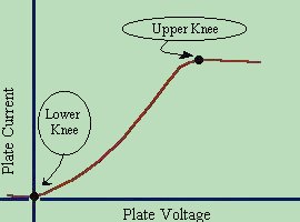 Assuming that the filament voltage of the tube is set, and that we are running
our tube into a fixed resistance load, we can increase the plate current by
increasing the plate voltage. Normally when plotting (or drawing) an operational
curve for a tube, we assume that the filament is held constant, and the plate
voltage is raised. As the plate voltage rises, so does the plate current.
We do note, however, that there is a minimum and maximum point, at which the
curve is no longer linear ( in a straight line ). We call the minimum point
the "lower knee" and the maximum point the "upper knee" of the curve. The
saturation point occurs at the beginning of the upper knee, while the cut-off
point occurs at the beginning of the lower knee. Under normal conditions,
we usually operate the tube within the linear portion of the curve.
Assuming that the filament voltage of the tube is set, and that we are running
our tube into a fixed resistance load, we can increase the plate current by
increasing the plate voltage. Normally when plotting (or drawing) an operational
curve for a tube, we assume that the filament is held constant, and the plate
voltage is raised. As the plate voltage rises, so does the plate current.
We do note, however, that there is a minimum and maximum point, at which the
curve is no longer linear ( in a straight line ). We call the minimum point
the "lower knee" and the maximum point the "upper knee" of the curve. The
saturation point occurs at the beginning of the upper knee, while the cut-off
point occurs at the beginning of the lower knee. Under normal conditions,
we usually operate the tube within the linear portion of the curve.
Later, we will discuss the characteristic curves of various other components. Each type of component has a slightly different curve, which dictates how the component will operate under different conditions. Understanding these curves will give you a more thorough knowledge of how the component works, and insight as to what it will do when it fails. |
| (On The Following Indicator... PURPLE will indicate your current location) | ||||||||||||||||||||||||
| 1 | 2 | 3 | 4 | 5 | 6 | 7 | 8 | 9 | 10 | 11 | 12 | 13 | 14 | 15 | 16 | 17 | 18 | 19 | 20 | 21 | 22 | 23 | 24 | 25 |
| 26 | 27 | 28 | 29 | 30 | 31 | 32 | 33 | 34 | 35 | 36 | 37 | 38 | 39 | 40 | 41 | 42 | 43 | 44 | 45 | 46 | 47 | 48 | 49 | 50 |
| 51 | 52 | 53 | 54 | 55 | 56 | 57 | 58 | 59 | 60 | 61 | 62 | 63 | 64 | 65 | 66 | 67 | 68 | 69 | 70 | 71 | 72 | 73 | 74 | 75 |
| Otherwise - please click to visit an advertiser so they know you saw their ad! |
