

|
Now that you understand AND, NOT, NOR, and NAND gates, and can recognize them in both their discrete and block diagram forms, it is time to get complicated. No more hand holding. We are going to study - the Flip FLop. Contrary to populary opinion, a Flip Flop is NOT a shoe. That shoe would be called a Thong. A Flip Flop is an electronic circuit that flips to a one, then flops to a zero, then flips back to a one, and so forth. I gave actual part numbers and values so that if you wanted to, you could build this circuit yourself and watch the magic at work. You can build it out on a breadboard, or make a printed circuit board if you feel comfortable doing so. Either way - this is how the circuit works: 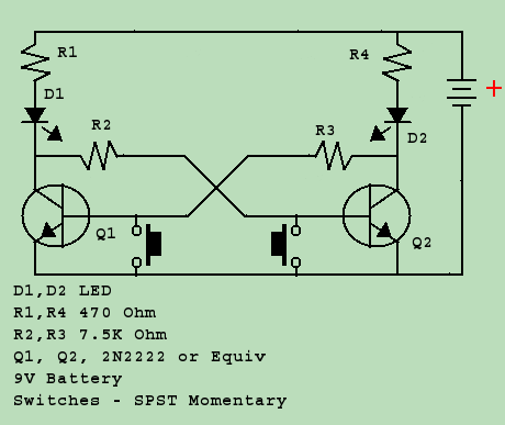 With 9V applied via the battery, one of the transistors will conduct (going high), which causes the other transister to remain off (going low). Which one turns on is somewhat random, as the circuit is symetrical. Again - this is a complicated circuit. You are going to have to slow down, and think through the movement of current through each individual part - our you'll get lost here.
For the sake of discussion, let us assume that Q1 is turned on. As Q1 turns on, current flows through R1, D1, and Q1. With current flowing through D1, it lights up, and we find we have a high on R2. Knowing that transistors act like NOT gates - if we have a High on R2 (input to Q2), you will have a LOW on Q2's output. If we push S1, it shorts the emitter-base connection of Q1, causing it to turn off. With Q1 turned off, we lose current flow through Q1 and D1 goes dark. R2 goes low. Now that R2 is low, we have a low on the input of the NOT gate Q2, which causes the collector voltage to rise, turning Q2 on, and causing D2 to light up. Which ever transistor is on can be turned off by simply grounding it's base through the push button, and we can continue the cycle turning one transistor on after the other. 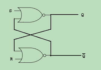 Note that this circuit looks very complicated. Again - in order to simplify things, we use BLOCK diagrams instead of schematic. Block logic diagrams, like the one on the right, are easier to follow, as they do not include every small component, and you don't have to think about the function and purpose of each component, only of the overall function of the circuit. If you look closely at the block diagram, it basically agrees with the schematic circuit drawn above. Note that this circuit looks very complicated. Again - in order to simplify things, we use BLOCK diagrams instead of schematic. Block logic diagrams, like the one on the right, are easier to follow, as they do not include every small component, and you don't have to think about the function and purpose of each component, only of the overall function of the circuit. If you look closely at the block diagram, it basically agrees with the schematic circuit drawn above.
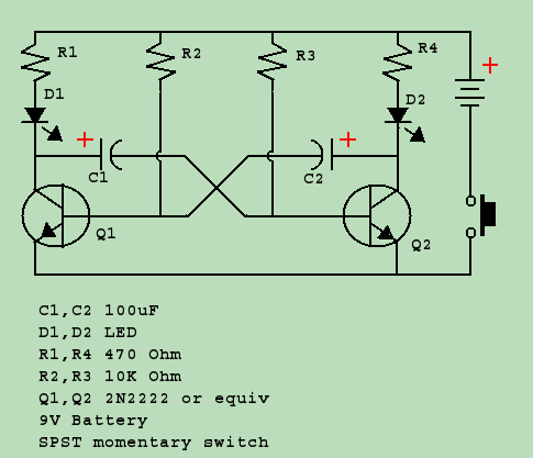 Next on our list of achievements is the multivibrator. A multivibrator is a type of flip flop that doesn't need a button to push. Once it starts running, it keeps flipping and flopping back and forth without any human intervention.
In short, a multivibrator works like an oscillator. 1,0,1,0,1,0,1 in a continuous loop, except it isn't a sine wave - it is a SQUARE wave. However, with proper filtering, the corners of the square wave can be rounded off to make a sine wave. A Multivibrator is the basis of a "Clock" circuit - used to set the timing of a microprocessor, found in every calculator, computer, and cell phone. In more modern radio systems it is used to set the frequency of the radio, and for many other puropses. To be certain when we start getting into digital circuity this complex, there are much easier and less expensive ways to do the job. They're called microchips. One microchip can contain thousands, even millions of discrete components. In the case of the multivibrator, there is the 555 timer chip. |
| (On The Following Indicator... PURPLE will indicate your current location) | ||||||||||||||||||||||||
| 1 | 2 | 3 | 4 | 5 | 6 | 7 | 8 | 9 | 10 | 11 | 12 | 13 | 14 | 15 | 16 | 17 | 18 | 19 | 20 | 21 | 22 | 23 | 24 | 25 |
| 26 | 27 | 28 | 29 | 30 | 31 | 32 | 33 | 34 | 35 | 36 | 37 | 38 | 39 | 40 | 41 | 42 | 43 | 44 | 45 | 46 | 47 | 48 | 49 | 50 |
| 51 | 52 | 53 | 54 | 55 | 56 | 57 | 58 | 59 | 60 | 61 | 62 | 63 | 64 | 65 | 66 | 67 | 68 | 69 | 70 | 71 | 72 | 73 | 74 | 75 |
[COURSE INDEX] [ELECTRONICS GLOSSARY] [HOME]
| Otherwise - please click to visit an advertiser so they know you saw their ad! |
