

Lesson 59 - Energy Conservation(and the Green Peace Mile)
Photoelectric is the term used to describe devices that change electricity into light, or light into electricity. A light bulb is "photo-electric", as is a light emitting diode. On the flip side, a photosensor or a photocell can take light in, and convert it into electricity. While we are thinking along these lines, let us look into piezoelectric devices. "Piezo-electric" is the word we use to describe components that convert electricity into motion, or motion into electricity DIRECTLY. We know that we can turn electricity into magnetism, and make the magnet move something, but that is indirect. By directly - we mean there is no magnetism, or other form of energy involved. Piezoelectric devices go from electricity straight to movement, or from movement straight to electricity. There are a few devices that do this. One such device is a crystal. 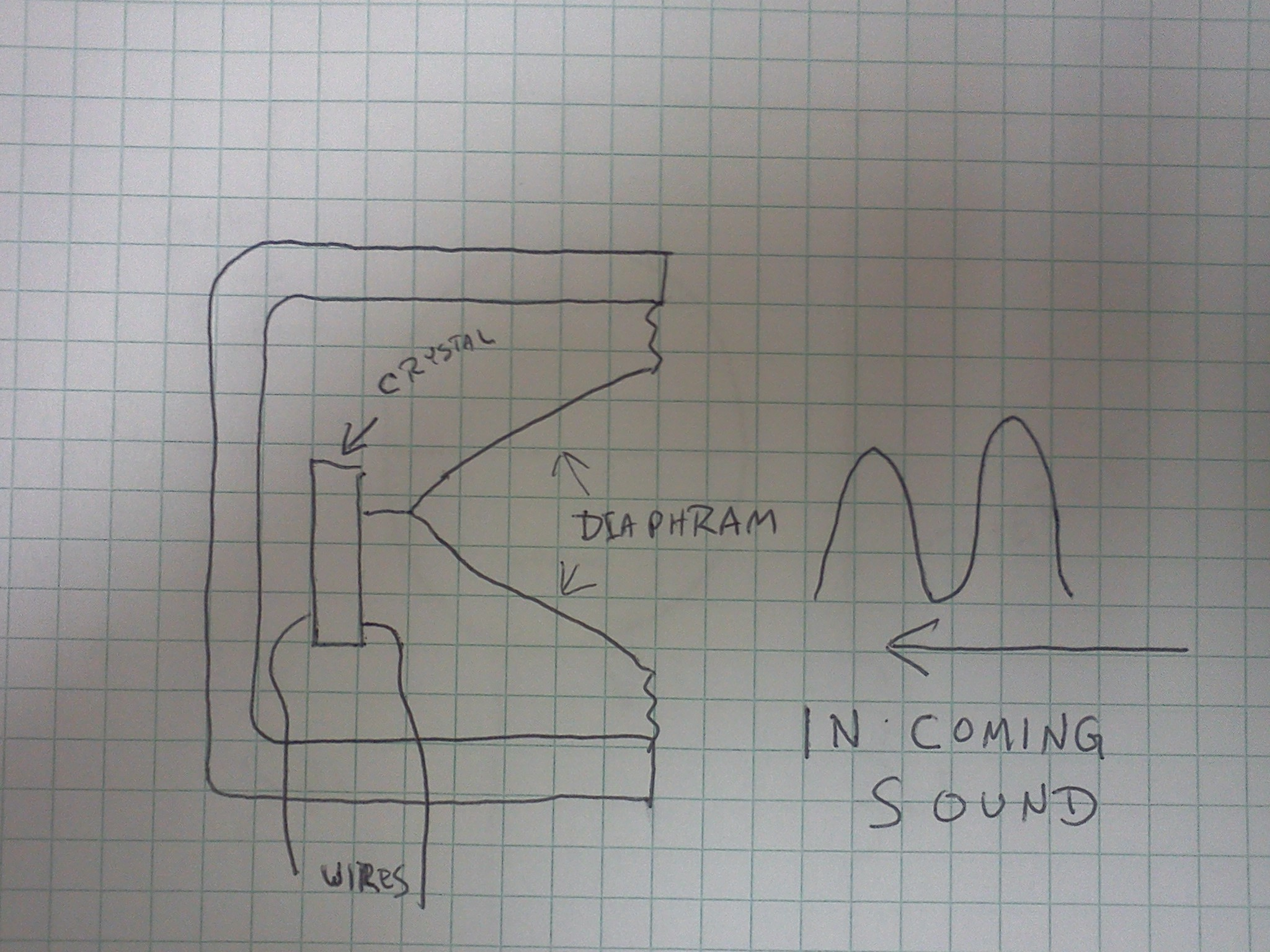 While there are many different types of crystals, it has been found that certain crystals have an interesting effect, in that when they are mechanically compressed, they "generate" electricity. Quartz, Rochelle salt, barium titanate or lead zirconate crystals are the most commonly used in electronics "crystals". Upon applying mechanical stress, they generate an electrical charge, and upon receiving an electrical charge, they will expand and contract. How is this useful? While there are many different types of crystals, it has been found that certain crystals have an interesting effect, in that when they are mechanically compressed, they "generate" electricity. Quartz, Rochelle salt, barium titanate or lead zirconate crystals are the most commonly used in electronics "crystals". Upon applying mechanical stress, they generate an electrical charge, and upon receiving an electrical charge, they will expand and contract. How is this useful?
Early on it was noted that it didn't take very much "stress" to make certain crystals produce electricity (or affect a voltage applied to them externally). Merely by speaking, they would generate low voltage signals. If amplified by a cone type diaphram, they would make enough voltage to be amplified, and usable for electronic circuits. 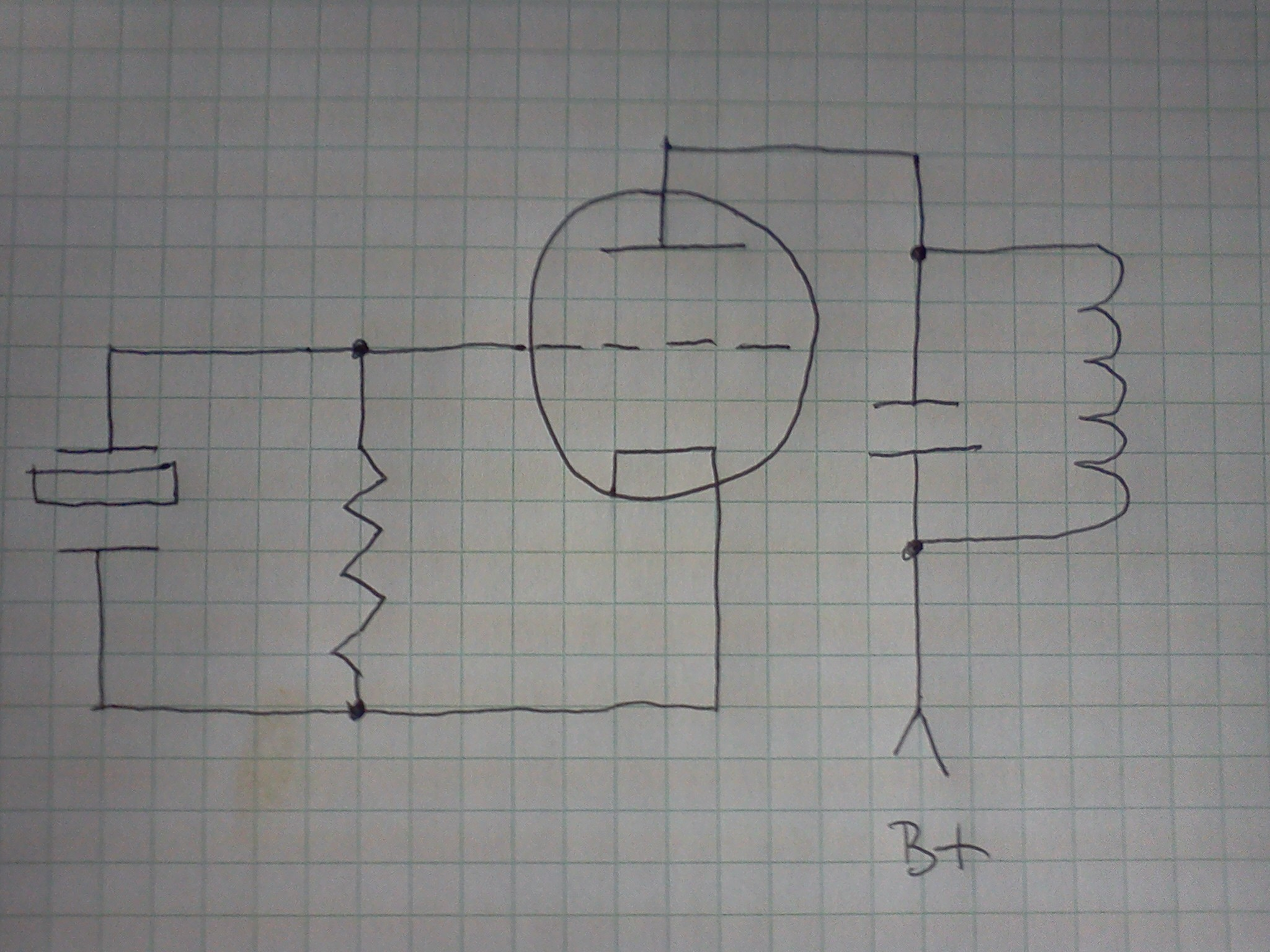 It stands to reason that if these crystals operate in both directions, that it might be possible to use them within oscillator circuits. Apply an alternating voltage to them, and it makes them vibrate. When they vibrate, they generate an alternating voltage. It almost sounds as if simply by attaching a battery, they will oscillate on their own. They almost do! It stands to reason that if these crystals operate in both directions, that it might be possible to use them within oscillator circuits. Apply an alternating voltage to them, and it makes them vibrate. When they vibrate, they generate an alternating voltage. It almost sounds as if simply by attaching a battery, they will oscillate on their own. They almost do!
Along the way, they found out that differing crystals liked to "oscillate" at different frequencies, and that the frequency was directly proportional to the SIZE (specifically the thickness) of the crystal. So by making a crystal thinner, they could increase the frequency. By using a thicker crystal, they could decrease the frequency. When alternating current is applied, the crystal compresses and expands - or "vibrates". The natural frequency of a crystal's vibrations, determined by its size, is far more constant than the oscillations in the typica LC tank circuit. Since the thinner the crystal is, the faster it vibrates, they could increase the frequency of a tuned circuit simply by shaving (sanding) off some of the crystal material. The crystal basically takes the place of the tank circuit! It did have some setbacks (range of frequencies), but had the MAJOR advantage of repeatable frequency. As such - it was far more frequency "STABLE" than any other circuit of its day. Now to look at the Crystal Oscillator you were promissed:
B+ passes through the plate coil to the plate. Current then flows (Negative to positive) from the (grounded) anode to the plate passing through the grid. We now have a more positive signal on one side of the crystal than on the other. Now the crystal does its thing (the shimmy shimmy shake), which then pushes back in the other direction, starting an agitating effect, swinging back and forth, at the same time applying that shimmy shimmy signal to the grid of the tube. As the grid swings back and forth, it causes the plate current to swing back and forth as well. There it is. Easy, straightforward, and no complications. The problem is - how do we adjust the frequency of this? This problem was answered in the "Pierce Oscillator". 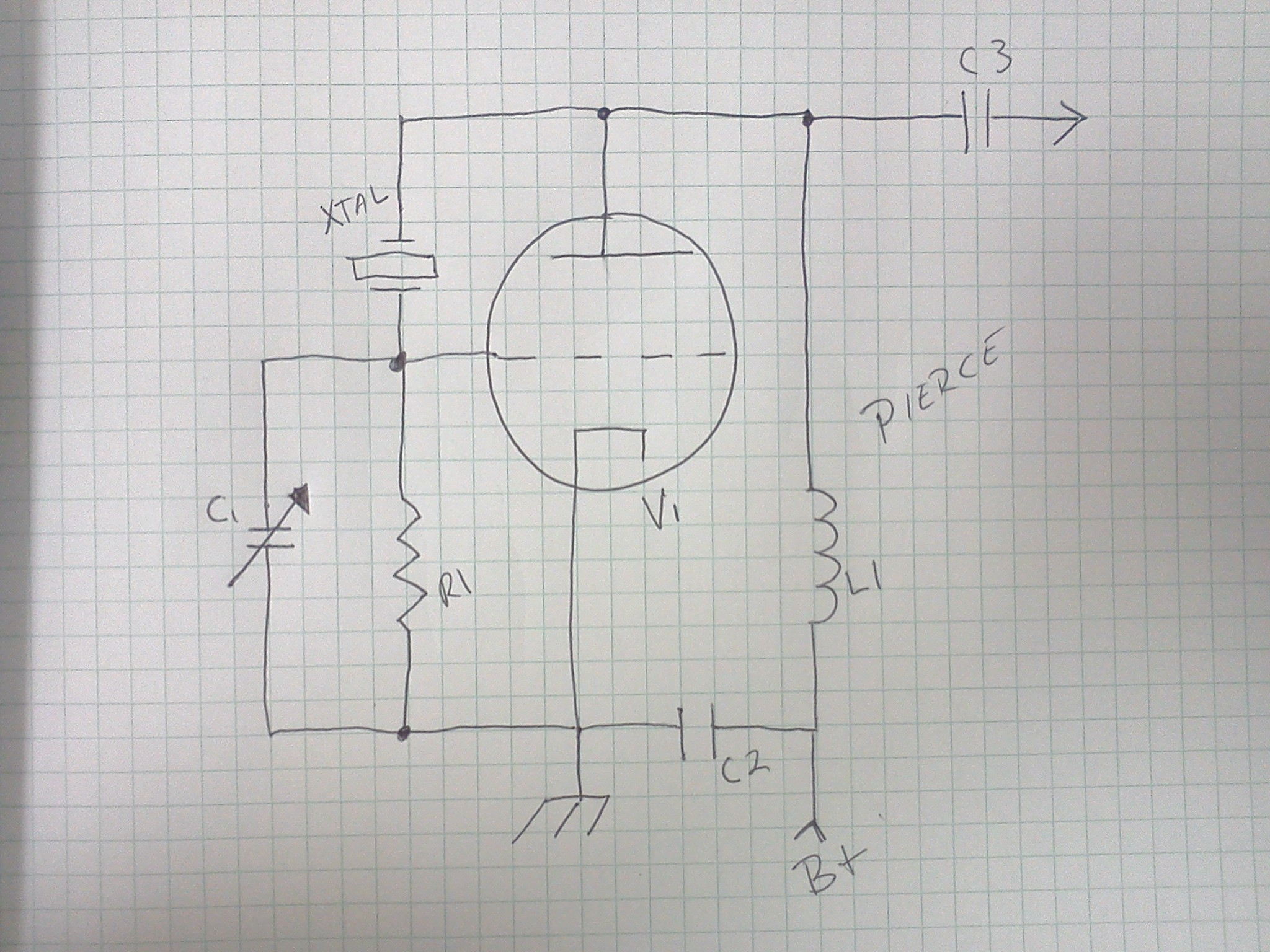 The Pierce Oscillator is a modified Crystal Oscillator, with a tuning capacitory added. In this PARTICULAR Pierce type design, the crystal (XTAL) is connected directly between the plate and grid. B+ goes through the plate coil, feeding the plate. Current flows through the tube, and activates the Crystal, which begins its natural swing. That swing is "slightly" altered by the capacitor C1, which being in parallel with the grid resistor R1, wants to do its own swing thing. In this manner, the exact frequency of the tuned circuit will be roughly the crystal frequency, being varied by the amount of the RC time constant developed between R1 and C1. The Pierce Oscillator is a modified Crystal Oscillator, with a tuning capacitory added. In this PARTICULAR Pierce type design, the crystal (XTAL) is connected directly between the plate and grid. B+ goes through the plate coil, feeding the plate. Current flows through the tube, and activates the Crystal, which begins its natural swing. That swing is "slightly" altered by the capacitor C1, which being in parallel with the grid resistor R1, wants to do its own swing thing. In this manner, the exact frequency of the tuned circuit will be roughly the crystal frequency, being varied by the amount of the RC time constant developed between R1 and C1.
While I could quickly get you to how the Pierce oscillator works, you are going to have to wait just a bit before we get to the monostable multivibrator. Digital electronics will take a bit of a learning curve, but rest assured - we are nearly there! Note that crystals are current sensitive. If you try to pump too much current through a crystal, it will crack, warp, or otherwise just not work anymore. As an engineer once told me, "Electricity is a bunch of smoke and mirrors. If you do something wrong, it will break the mirror and let the smoke out - then it doesn't work anymore." Many a time I've had to fix a transmitter (like on a wireless microphone) that simply had a broken crystal - simply because the operator was careless (or just plain clumbsy) and dropped it on the floor.  |
| (On The Following Indicator... PURPLE will indicate your current location) | ||||||||||||||||||||||||
| 1 | 2 | 3 | 4 | 5 | 6 | 7 | 8 | 9 | 10 | 11 | 12 | 13 | 14 | 15 | 16 | 17 | 18 | 19 | 20 | 21 | 22 | 23 | 24 | 25 |
| 26 | 27 | 28 | 29 | 30 | 31 | 32 | 33 | 34 | 35 | 36 | 37 | 38 | 39 | 40 | 41 | 42 | 43 | 44 | 45 | 46 | 47 | 48 | 49 | 50 |
| 51 | 52 | 53 | 54 | 55 | 56 | 57 | 58 | 59 | 60 | 61 | 62 | 63 | 64 | 65 | 66 | 67 | 68 | 69 | 70 | 71 | 72 | 73 | 74 | 75 |
[COURSE INDEX] [ELECTRONICS GLOSSARY] [HOME]
| Otherwise - please click to visit an advertiser so they know you saw their ad! |
