

Lesson 52 - Filter Circuits Part 2Now that you know basically what a filter is, what it does, and how the math is caclulated for building one - let's see some more complex forms of filters, and see if you can recognize what they are and what they do. 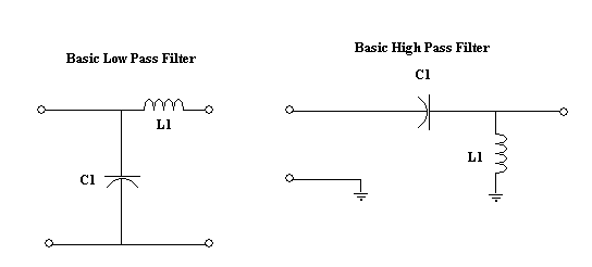 Of course the basic filter is easy to recognize. It can have coils, caps, and/or resistors in a combination that will pass certain frequencies while at the same time blocking others. But what happens if more caps and coils are added? Simple - they do more filtering. One of the more common filter networks is the one pictured below, the " Pi " filter network. 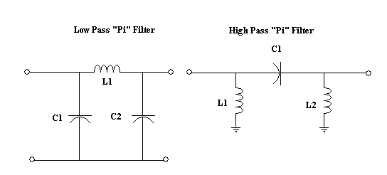 It is called the Pi filter, for one simple reason, it looks alot like the greek symbol Pi ( π ). It is called the Pi filter, for one simple reason, it looks alot like the greek symbol Pi ( π ). Certainly someone with a technical eye can see the indisputable resemblance! Note that it does NOT in any way resemble a pie, although my wife makes some very good ones and here is an example of her artwork ----------------------------> 
The Pi filter does the same thing that any other filter does, although with the added components, it has the advantage of filtering at a sharper angle (meaning they do a better job of filtering). The steeper the angle of cut-off, the faster and better the filter is. 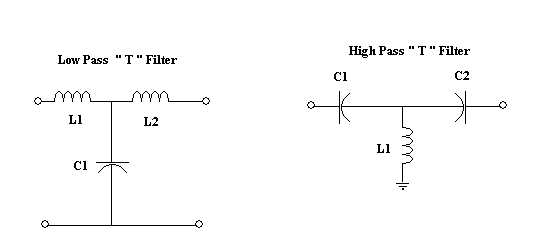 A second common filter configuration is called the " T " filter - again, because it is shaped like the letter T. Keep in mind, that in all these filters, the basic rule applies - Capacitor High in the circuit = High Pass, Capacitor Low in the circuit = Low Pass. These are basic passive filters. Some filters you may learn about in the future may include amplifying devices in their filtration, each giving them different properties of filtration, but in the end - the basics are still the same. So whether you are looking at a Bessel, Butterworth, Chebychev, Legrande, or Zolatarev filter (listed in alphabetical order - for no particular reason) - simply looking at the placement of the caps and coils will indicate how the filter should react. But what happens if you put a high pass and low pass filter together? You get something called a Band Pass filter! 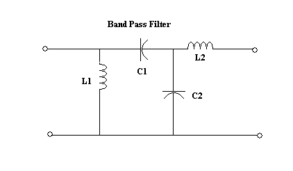 Looking at the picture, see if you can follow the line of thought: Let's say we have a wide band signal coming in, that includes all frequencies from DC to Blue Light (hint - that's a lot of frequencies). This is the beginning stage of say, a radio receiver, that we want to allow only one small band of frequencies in - for instance 580 to 590 Megahertz. So our wide band signal comes into the antenna and is fed to the input of our filter. It hits the first two components - a capacitor (C1) and a coil (L1). This cap and coil are chosen as a High pass filter, to allow all frequencies ABOVE 580 MHz into the receiver. That's great - but we don't want frequencies higher than 590 MHz coming in - so we add - RIGHT BEHIND OUR FIRST FILTER - a second filter, (C2 and L2) that act as a Low pass filter, keeping any frequencies above 590 MHz out. So all frequencies ABOVE 580 and BELOW 590 are allowed to pass through the filter, but all other frequencies are kept out. Typically, but not necessarily, both the capacitors in this circuit are close to the same value, and both the coils are close to the same value. This is because both circuits have the same cut-off frequency, but one is a high pass, and the other is a low pass. See - that didn't take a lot of math to understand! I almost forgot - but I'm sure you would have reminded me. How can you have a band PASS filter without a band STOP filter? What happens if instead of needing one frequency or group of frequencies to be allowed into the next stage of your radio - what you actually need is a certain frequency or group of frequencies deflected and sent straight to ground - so that the don't enter your radio at all? As is sometimes the case, you may have a very strong signal that would interfere with the normal operation of your circuit. This signal can be squashed by the copious use of a band-stop filter. This will also be a good time to introduce a special kind of a filter circuit - called a "tank" circuit. The tank circuit contains a capacitor and an inductor in parallel with each other. In this configuration, the low frequency signal tries to go through the cap, but is blocked, so it turns around and goes through the coil instead. The high frequency signal tries to go through the coil, but is bucked as well, and is forced to turn tail and go by way of the capacitor. As such, it is said that the signal sloshes around inside the circuit like so much water sloshing around in a tank.... hence - a tank circuit. 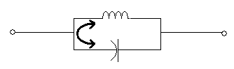
Clearly this type of circuit has some great advantages. By its very nature - it is a band pass filter, that is tuned to a specific frequency, as set by the values of the cap and coil. But what happens if we take this band pass filter, and turn the output of it toward ground? 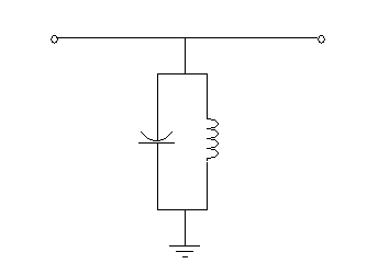
This is exactly how a band stop filter works. A tank circuit ( or any other kind of band pass filter for that matter ), whose output goes directly to ground, will force the specified frequencies to leave the circuit quite abruptly, and go their way to be buried in the depths of the earth. Often, when this type of circuit is employed, it is preceded and followed by other filter circuits. In the end, though, it is just a filter, and like any other filter, is designed to pass certain frequencies, and block out others. Note - if ever you are repairing a circuit of this type, pay very close attention that you replace the defective component with the exact same component. I could tell you a story about the vertical circuit of a big screen television, but I won't. Let's just say if you use a value that is close, but not right on the money - you may not be happy with the outcome. 
|
| (On The Following Indicator... PURPLE will indicate your current location) | ||||||||||||||||||||||||
| 1 | 2 | 3 | 4 | 5 | 6 | 7 | 8 | 9 | 10 | 11 | 12 | 13 | 14 | 15 | 16 | 17 | 18 | 19 | 20 | 21 | 22 | 23 | 24 | 25 |
| 26 | 27 | 28 | 29 | 30 | 31 | 32 | 33 | 34 | 35 | 36 | 37 | 38 | 39 | 40 | 41 | 42 | 43 | 44 | 45 | 46 | 47 | 48 | 49 | 50 |
| 51 | 52 | 53 | 54 | 55 | 56 | 57 | 58 | 59 | 60 | 61 | 62 | 63 | 64 | 65 | 66 | 67 | 68 | 69 | 70 | 71 | 72 | 73 | 74 | 75 |
[COURSE INDEX] [ELECTRONICS GLOSSARY] [HOME]
| Otherwise - please click to visit an advertiser so they know you saw their ad! |
