

Note: It is assumed that if you are taking this course, that you have some


knowledge of both DC and AC electronics theory, and know the basic operation of a vacuum tube.


If you are weak in these areas, I suggest you take my courses on these subjects


before proceding with the rest of the course.


This course, as it is presently in the process of


being written. It is by no means finished.  Comments are invited.


Use the "EMAIL" link at the bottom.  This will aid me in the editing process.


 Also - 1 error noted to date:


1) Due to the fact that NO BROWSER yet follows the HTML standard published by the W3C,


Greek letters, commonly found in electronics, can not be displayed by their proper HTML command.


I have written the course so that a MAJORITY of systems will show these greek characters fine.


Please let me know if you are experiencing problems viewing the greek letter OMEGA below.
W Now, on with the course. Cavity ResonatorsBefore going into the specifics of how a Klystron tube works, we must first understand it's basic parts. Which reminds me of a story.... I once had an "oldtimer" friend tell me that he once had to build a dummy load for a radar unit. He explained that he didn't have all the necessary components to perform the mission at hand, and proceded to tell me how he made the dummy load out of an old coffee can he procured from the mess hall. (Chester, if you're out there, this chapter is dedicated to you). At first, I thought he was about to explain a mineral oil filled can with a high wattage 50 W carbon resistor (commonly used in HF work) , but after hearing his description of the device, I understood that he had built something that is commonly called a CAVITY RESONATOR. The theory of operation is something like this. If a 2 wire transmission line cut to 1/4 wavelength is shorted at the far end, it acts like a parallel resonant circuit. A signal generator (i.e. transmitter) will see this as a high impedance at the resonant frequency. Any parallel resonant circuit acts as a high resistance to a signal source at the resonant frequency. 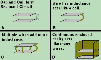
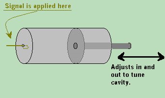 Now let us examine Chester's coffee can. The basic design of the coffee can dummy load is not altogether different from figure (D) above. The difference is that it is round, and that it has a rod connected to one end, such that we can move one of the plates. In this manner, we can change the distance between the capacitive plates, and hence, the capacitance within the tank circuit. By doing so, we can change the resonant frequency, and tune the cavity to have maximum resistance at a given frequency. The signal is applied at one end by a loop of wire, which transmits the signal into the cavity. If tuned properly, the cavity will present a very high resistance to the transmitter signal, and in essence, acts as a dummy load. The frequency at which it resonates is a direct result of the distance between the plates. From this we learn that the frequency of a resonant cavity is determined by its physical dimensions. The shape can be cylindrical, cubical, spherical, pyramid shaped, or otherwise, but the shape will also determine the circuits effective Q. Now let us examine Chester's coffee can. The basic design of the coffee can dummy load is not altogether different from figure (D) above. The difference is that it is round, and that it has a rod connected to one end, such that we can move one of the plates. In this manner, we can change the distance between the capacitive plates, and hence, the capacitance within the tank circuit. By doing so, we can change the resonant frequency, and tune the cavity to have maximum resistance at a given frequency. The signal is applied at one end by a loop of wire, which transmits the signal into the cavity. If tuned properly, the cavity will present a very high resistance to the transmitter signal, and in essence, acts as a dummy load. The frequency at which it resonates is a direct result of the distance between the plates. From this we learn that the frequency of a resonant cavity is determined by its physical dimensions. The shape can be cylindrical, cubical, spherical, pyramid shaped, or otherwise, but the shape will also determine the circuits effective Q.
|

This Course was written by Ray Dall © All Rights Reserved.
This page and all it's content Copyright, Trademarks, Intellectual Properties
and other legal issues 1994, 1995, 1996, 1997, 1998, 1999, 2000, 2001, 2002, 2003, 2004, 2005, 2006 Ray Dall.
All Rights Reserved.
And for what it's worth... this page was last updated HexDate 01-11--7D1
